Skills Laboratory: How to determine and interpret the mean electrical axis
You can easily detect most arrhythmias on physical examination, but you'll need an electrocardiogram to identify an arrhythmia's exact nature.
You can easily detect most arrhythmias on physical examination, but you'll need an electrocardiogram (ECG) to identify an arrhythmia's exact nature. Obtain an ECG anytime a patient has an arrhythmia that isn't associated with respiration, has irregular pulses, or has a history suggestive of an arrhythmia, such as a collapse episode. To diagnose arrhythmias, a single lead II ECG tracing is generally all you need. However, to detect changes in the mean electrical axis, a multilead ECG is necessary.
Identifying abnormalities in the mean electrical axis helps you diagnose conduction abnormalities, detect ventricular hypertrophy, and differentiate the origin of arrhythmias. Further, a multilead ECG will help you rule out an artifact as the cause of electrocardiographic abnormalities seen in a single-lead tracing. Although thoracic radiography and echocardiography have higher sensitivity for diagnosing chamber enlargement, an abnormal ECG may signify that additional diagnostic tests are indicated. Additionally, an intraventricular conduction disturbance can only be diagnosed with an ECG.
Genesis of the ECG
An ECG is a surface recording of the net or average electrical activity of the myocardium.1 Atrial depolarization is represented by the P wave, and ventricular depolarization is represented by the QRS complex. Electrical activity of the conduction system (atrioventricular node, bundle branches, and Purkinje fibers) is not detectable by the surface ECG and occurs during the flat P-R segment.
Myocardial cells are polarized during the resting state, with the inside of the cell negatively charged relative to the outside. Depolarization results from ion shifts that cause the outside of the cell to become negatively charged relative to the inside. These ion shifts move across the myocardium in an orderly wave front. Normal depolarization of the heart occurs in a fairly regular sequence, which provides the familiar ECG tracing.
The standard multilead system used in veterinary medicine is the hexaxial lead system formed by six limb leads (Figure 1).2 Leads I, II, and III are bipolar leads, meaning that they have a positive pole and a negative pole. Leads aVR (augmented voltage right arm), aVL (augmented voltage left arm), and aVF (augmented voltage left foot) are known as unipolar leads. Unipolar leads have only a positive pole; the activity of the positive pole is compared with the average of two other leads. By convention, the label for a lead is placed at the position of its positive pole on the ECG lead diagram.

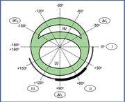
Figure 1. A frontal plane diagram of a hexaxial lead system (I, II, III, avR, avL, avF) superimposed over a short-axis view of the heart (RV = right ventricle, LV = left ventricle). The double-lined arc from 0 to +160 degrees indicates the normal mean electrical axis in cats. The solid bar arc from +40 to +100 degrees indicates the normal mean electrical axis in dogs.
Each ECG lead records the electrical activity of the heart relative to that lead. A wave of depolarization that is traveling toward the positive pole of a lead will result in a positive deflection in that lead. Conversely, a wave of depolarization that is traveling away from a positive lead will result in a negative deflection in the lead. ECG leads are positioned around the heart at different angles, which is why the waveform recorded by each lead appears different.
The amplitude (height) of an ECG R wave is proportional to how parallel the wave front of depolarization is to that lead. When a wave of depolarization is moving toward the positive pole, the more directly parallel the wave front is to the lead, the taller the R wave will be. The more perpendicular the wave of depolarization is, the smaller the resulting R wave will be. A wave front of depolarization that is traveling 90 degrees perpendicular to a lead will result in an isoelectric QRS complex. Isoelectric means that the positive deflection of the R wave and the negative deflection of the Q and S waves are equivalent. Stated mathematically, the positive and negative deflections of the QRS complex sum to zero.
The mean electrical axis
The mean electrical axis is the principal vector of ventricular depolarization.3 It represents the sum of all of the waves of depolarization that are occurring simultaneously. The mean electrical axis normally points toward the left ventricle, as this is the larger of the two ventricles. Deviations of the mean electrical axis result from either right ventricular hypertrophy or a block in the intraventricular conduction system. An intraventricular conduction block will result in deviation of the mean electrical axis toward the ventricle that is expected to be depolarized by the bundle branch or fascicle that is blocked.
The hexaxial lead system is arranged around the heart in essentially a short-axis plane, which is referred to as the frontal plane. In this plane, the left ventricular apex is oriented generally toward the positive pole of lead II. The circumference of the frontal plane is labeled in degrees (0 to +180 and 0 to -180). The normal range of the mean electrical axis in dogs is +40 to +100 degrees and in cats is 0 to +160 degrees (Figure 1). In dogs, a right axis shift is defined as a mean electrical axis between +100 and -90 degrees. In cats, a right axis shift occurs when the mean electrical axis is between +160 and -90 degrees. A left axis shift occurs in dogs when the mean electrical axis is between +40 and -90 degrees and in cats when the mean electrical axis is between 0 and -90 degrees.
To determine the mean electrical axis, you must obtain a six-lead ECG from a patient positioned in right lateral recumbency with the limbs perpendicular to the long axis of the patient's body. Four basic methods exist for estimating the mean electrical axis. The first two methods are considered more accurate, while the second two are reasonable approximations.
1. Find an isoelectric lead—Identify a lead in which the positive and negative deflections of the QRS complex are equal. The lead that is perpendicular to the isoelectric lead is the lead that will identify the mean electrical axis (Figure 2). If the QRS complex is predominantly positive in the perpendicular lead, then the mean electrical axis is directed toward the positive pole. If the QRS complex is negative, then the mean electrical axis is directed away from the positive pole.
If no lead is isoelectric, use one of the other methods. If two leads are isoelectric, select the lead that has the smaller QRS complex deflections to determine the mean electrical axis. In the unusual instance that all of the leads are isoelectric, the mean electrical axis cannot be determined because it lies outside of the frontal plane of the hexaxial lead system.

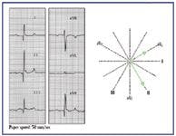
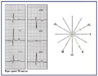
Figure 2. The mean electrical axis can be easily identified when an isoelectric lead is present. Examination of this ECG indicates that lead aVL is isoelectric. Lead II is perpendicular to aVL and is predominantly positive. Therefore, the mean electrical axis is normal at +60 degrees.
2. Use the lead graphing method—Measure the net deflections of leads I and III (Figure 3). From the baseline (the P-R segment), count the number of upwardly deflected boxes in the R wave, and then subtract the number of downwardly deflected boxes in the Q and S waves. Plot the net deflection on each lead, and then draw a perpendicular line through each of these points. The point where the lines from leads I and III intersect is the mean electrical axis. Any two leads can be used, but leads I and III are most often used.


Figure 3. The mean electrical axis can be identified by graphing the net deflections of leads I and III. The positive deflections of the R waves are measured from the baseline (P-R segment). The negative deflections of the Q and S waves are similarly measured from the baseline. Perpendicular lines are drawn at +6 for lead I and -7 for lead III. Where the two perpendicular lines intersect is the mean electrical axis. This mean electrical axis is shifted to the left, consistent with a left anterior fascicular block. This is a common axis deviation in cats with cardiomyopathy.
3. Find the lead with the tallest R wave (Figure 4)—The mean electrical axis is within 30 degrees of the positive pole of the tallest R wave.

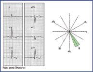
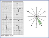
Figure 4. The approximate location of the mean electrical axis can be found by identifying the lead with the tallest R wave. The mean electrical axis will be within 30 degrees of the positive pole of this lead. In this ECG, lead II has the tallest R wave, indicating that the mean electrical axis is normal.
4. Use the quadrant graphing method4 —In this method, the hexaxial lead system is divided by leads I and aVF into four equal quadrants. Arrows are drawn on leads I and aVF in the direction of the predominant QRS complex deflection. For example, in Figure 5 the QRS complex in lead I is predominantly negative, so an arrow will be drawn toward the negative pole of lead I. Lead aVF is also predominantly negative, so an arrow will be drawn away from its positive pole. This would place the mean electrical axis in the upper right quadrant, indicating a right axis shift. The mean electrical axis can be further estimated by examining the relative size of the QRS complexes in leads I and aVF. The mean electrical axis will be closer to the larger of the two. Since lead aVF is more negative than lead I, the mean electrical axis will be closer to –90 degrees than to –180 degrees.
Figure 5. The mean electrical axis can be approximated by determining the quadrant that it lies within. In this ECG, lead I is negative, so the mean electrical axis must lie either in the upper or lower right quadrant. Lead aVF is also negative, so the mean electrical axis is in the upper right quadrant. This is a marked right axis shift in a cat with pulmonic stenosis and right ventricular hypertrophy.
If an estimate of the mean electrical axis is ambiguous with the latter two methods, then one of the more precise methods should be used to verify the results.
Abnormalities of the mean electrical axis
Table 1 summarizes the causes of various mean electrical axis shifts and their ECG characteristics. The mean electrical axis normally points toward the left ventricle because this is the largest mass of myocardium, so the surface ECG predominantly records its activity.4 Severe hypertrophy of the right ventricle will cause the electrical activity of the right heart to dominate over that of the left on the ECG, resulting in a right axis shift of the mean electrical axis. The ECG changes associated with left ventricular hypertrophy include increased R wave amplitude and a mild increase in QRS complex duration. Left ventricular hypertrophy does not usually cause a shift in the mean electrical axis because the left ventricle tends to enlarge in the direction of lead II.
Table 1 Abnormalities of the Mean Electrical Axis and Potential Underlying Causes
Intraventricular conduction defects cause a shift in the mean electrical axis toward the ventricle that is depolarized by the defective bundle branch or fascicle. The mean electrical axis shifts toward the defect because the myocardium that is normally depolarized by that portion of the conduction system must now be depolarized by slow myocyte-to-myocyte conduction. The increased time needed for depolarization results in the electrical activity of that region of myocardium predominating over that of the normal myocardium. The QRS complex that results from a bundle branch block can be quite abnormal in appearance, but it can often be distinguished from a ventricular premature complex by the appearance of a normal P wave preceding the QRS complex.
The two common causes of a right axis shift of the mean electrical axis are right ventricular hypertrophy (Figure 5) and right bundle branch block (RBBB). These two conditions are distinguished electrocardiographically by the duration of the QRS complex. Right ventricular hypertrophy is associated with a normal duration QRS complex, while RBBB results in a prolonged QRS complex duration because of slow myocyte-to-myocyte conduction. In dogs, RBBB is associated with a QRS complex duration of greater than 0.08 seconds (≥ 0.07 seconds in toy breeds). In cats, RBBB results in a QRS complex duration of greater than or equal to 0.06 seconds. Right ventricular hypertrophy can occur concurrently with RBBB, but it would be necessary to perform an echocardiogram to make this distinction.
Left bundle branch block (LBBB) does not usually cause a shift in the mean electrical axis. With LBBB, the left ventricle depolarizes by myocyte-to-myocyte conduction. As in the normal conduction system, this causes the left ventricle to predominate over the right. Electrocardiographically, LBBB is characterized by a normal mean electrical axis with a prolonged QRS complex duration (> 0.08 seconds in dogs [≥ 0.07 in toy breed dogs] and ≥ 0.06 seconds in cats).
The right bundle branch terminates in the Purkinje fibers, which distribute to the right ventricular myocardium. The left bundle branch bifurcates into two widely branching anterior and posterior fascicles, which further subdivide into Purkinje fibers. Left anterior fascicular block is the most common conduction abnormality in cats and results in a marked left axis deviation of the mean electrical axis (Figure 3). It can accompany any form of feline cardiomyopathy, though hypertrophic cardiomyopathy is the most common. Left anterior fascicular block can also be seen with hyperkalemia and hyperthyroidism. Left anterior fascicular block is uncommon in dogs.
Left posterior fascicular block is the least common conduction disturbance and is a diagnosis of exclusion. It causes a right axis deviation with a normal duration QRS complex, so it must be distinguished from right ventricular hypertrophy by radiography and echocardiography.
Bundle branch and fascicular blocks are not hemodynamically significant and are generally not detectable on physical examination. However, they are frequently markers of underlying disease and signify the need to perform additional diagnostic tests to determine their cause.
Conclusion
Calculating the mean electrical axis is a simple and rapid diagnostic procedure that should be considered part of routine ECG analysis. Shifts in the mean electrical axis, in conjunction with radiographic changes, can help you diagnose cardiac chamber enlargement and conduction defects. So careful attention to the mean electrical axis may be particularly helpful in practices that do not have access to echocardiography. However, it is important to remember that cardiac chamber enlargement can occur without a concurrent shift in the mean electrical axis and that changes in the mean electrical axis occasionally occur in the absence of overt cardiac disease.
Deborah M. Fine, DVM, MS, DACVIM (cardiology)
Department of Veterinary Medicine and Surgery
College of Veterinary Medicine
University of Missouri
Columbia, MO 65211
REFERENCES
1. Tilley LP. Generation of the electrocardiogram: basic principles. In: Essentials of canine and feline electrocardiography: interpretation and treatment. 3rd ed. Philadelphia, Pa: Lea & Febiger, 1992;1-18.
2. Kittleson MD. Electrocardiography: basic concepts, diagnosis of chamber enlargement, and intraventricular conduction disturbances. In: Kittleson M, Kienle R, eds. Small animal cardiovascular medicine. St. Louis, Mo: Mosby, 1998;72-94.
3. Miller MS, Tilley LP, Smith FWK, et al. Electrocardiography. In: Fox P, Sisson D, Moise N, eds. Textbook of canine and feline cardiology: principles and clinical practice. 2nd ed. Philadelphia, Pa: WB Saunders Co, 1999;67-106.
4. Beardow AW. Electrocardiography. In: Abbott J, ed. Small animal cardiology secrets. Philadelphia, Pa: Hanley & Belfus, 2000;106-114.


Podcast CE: Canine cardiology: the practical guide to the mitral valve patient
July 19th 2023Learn about the prevalence of myxomatous mitral valve disease, guidelines for staging heart disease, proactive diagnostic workup, the importance of spironolactone and aldosterone blocking, and the benefits of combination therapy for improved outcomes in canine patients
Listen