How to obtain the best dental radiographs
The most important thing you can do to increase the quality of dental care in your practice is to use dental radiography when evaluating patients presented for routine dental care or dental problems.
Dental radiographs provide practitioners with a tremendous amount of information. The most important thing you can do to increase the quality of dental care in your practice is to use dental radiography when evaluating patients presented for routine dental care or dental problems. In addition, the AAHA Dental Care Guidelines for Dogs and Cats state that preoperative and postoperative dental radiographs are mandated for all extractions.1 Furthermore, standard radiographic views of the skull are inadequate, and full-mouth dental radiographs are an essential step in dental cleaning and are necessary for accurate oral evaluation and diagnosis.
In this article, I'll provide information to help you avoid common dental radiography errors and to perfect your dental radiography techniques by reviewing the basics of positioning, exposure, and development, including how to capture hard-to-image teeth in dogs and cats.
THE RIGHT PLACEMENT, THE RIGHT TIMING
To obtain a diagnostic radiograph, it is crucial to get the patient, film, and beam head in just the right position and set the correct amount of X-ray exposure. Follow this systematic approach.
Step 1: Patient positioning
The first step in creating high-quality dental images is to ensure correct patient positioning.2-6 Sand bags, V-shaped troughs or holders, and other implements will aid in stability and patient placement. Make sure the area of interest is appropriately positioned in the radiographic beam. Except in rare instances, the object or tooth to be radiographed is positioned on the up side. To help you determine the bisecting angles, position the patient as follows:
- Mandibular premolar and molar teeth: Place the patient in lateral recumbency with the side to be imaged up.
- Maxillary teeth: Place the patient in ventral recumbency.
- Mandibular canine and incisor teeth: Place the patient in dorsal recumbency.
Once an operator is proficient in visualizing the correct bisecting angle, several maxillary images can be obtained with the patient in lateral recumbency, which avoids repositioning the patient numerous times during procedures.
Step 2: Film placement
Film placement in veterinary dentistry can be challenging because of the anatomy of the tooth roots and the inability to see the roots. Correct film placement minimizes retakes.
When standard dental film (e.g. Eastman Kodak Company HSD/Dental Products) is used (Figure 1), an embossed dot (or dimple) is evident on the corner of the film. The side of the film with the palpable dimple should be placed toward the X-ray beam; with most film types, this side of the film is typically white. The opposite or back side of the film is usually colored.


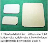
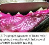
Place the film in the mouth, ensuring that the entire tooth (including the root) will be imaged. The most common sizes of film used in veterinary dentistry are size 4 and size 2. Size 4 film is used for large patients, whole quadrants, or exposing full-mouth radiograph sets. Size 2 is used for individual teeth or for smaller patients. Sizes 0 and 1 are occasionally used for small and pediatric patients. Size 3 is known as bite wing and is rarely used in veterinary dentistry. The roots are much longer than the crowns in veterinary patients. This is especially true of canine teeth, which have roots that are at least twice as long as the visible crown. Always err on the side of having the film too far into the mouth to ensure you capture the complete root structure. In addition, place the film as close as possible to the tooth or teeth of interest (generally touching the tooth and gingiva) to minimize distortion (Figure 2).


Step 3: Positioning the beam head
Accurate beam head placement in relation to the patient and film is the most challenging aspect of veterinary dental radiography. However, once correct positioning is mastered, dental radiography becomes much easier and more efficient.
There are two common techniques for positioning the beam head in dental radiography—the parallel and the bisecting angle techniques.
Parallel technique. By strict definition, this technique is used only on the mandibular premolar and molar teeth. All other teeth have anatomical structures (palate or mandibular symphysis) that preclude parallel film placement. For this technique, place the film parallel to the tooth and perpendicular to the X-ray beam (Figure 3).7 This technique is similar to standard radiographic techniques for other parts of the body (e.g. spine, thorax). The parallel technique provides the most accurate image.
Bisecting angle technique. This positioning technique is the most common one used in veterinary dentistry since the parallel technique cannot be used for most of the teeth. For this technique, place the film as parallel as possible to the tooth root. Then measure or approximate the angle between the long axis of the tooth root and film. Finally, divide this angle in half (bisect the angle) and direct the incident X-ray beam perpendicular to this imaginary angle (Figure 4) (see "Understanding bisecting angles").7


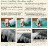
Understanding bisecting angles
Step 4: Setting the exposure
This step involves determining the amount of radiation that will be used to expose the image. Exposure settings in dental radiography differ from those in standard radiography in that the kVp and mA are held constant. Only the time is adjusted.


Table 1 Dental Radiography Technique Charts
Dental radiography machines used in people* require manually setting the exposure; you will need to create a technique chart for your system. This chart is similar to the one used for a standard radiography machine, except only one variable, exposure time, needs to be adjusted. Start with the sample charts provided, and adjust to your individual machine (Table 1). Note that the settings for direct digital systems (sensors) are much lower than those for standard film (see "Digital dental radiography advantages and disadvantages"). With indirect digital systems, such as phosphor plate, the settings are similar to or higher than those for standard film, and phosphor plates have a wide exposure range.

Digital dental radiography advantages and disadvantages
If you are using a computer-controlled system,** set the controls for the species, size of the patient, and tooth to be imaged. If the setting is proper and the exposure is incorrect, the easiest way to make corrections is to change the f setting. By pressing the f button, both numbers in the windows will go up. The one on the left is the f number, and the one on the right is the exposure time. If you continue to press the button, it will continue to increase the exposure time until the f number reaches 9, when it will markedly decrease and the f number will go back to 1. If the radiograph is overexposed (too dark), decrease the f number by 1. If it is underexposed (too light), increase the number by 1. Continue this process until you have correct film exposure. Generally, the f number will be the same for all radiographs on a given machine.
Step 5: Exposing the radiograph
It is strongly recommended that everyone leave the room before exposing the radiograph to reduce X-ray exposure. If this is not possible, stand at least 6 ft away and to the side of the tube head—not in front of or behind it—at a 90-to 130-degree angle to the primary beam. Some practices use outdated human dental X-ray units. These units are not recommended because of the increased radiation exposure (scatter) and, in some cases, the inability to achieve a short enough exposure time for direct digital systems. Regardless of the type of unit used, regular inspections and radiographic monitoring should be performed.
Most dental radiography units have a hand-held switch. When exposing radiographs, if you release finger pressure on the switch during the exposure, the production of X-rays will stop. On a manually adjusted dental radiography unit, this will result in an underexposed or light radiograph, while on a computer-controlled dental radiography unit, an error message will illuminate, and you must restart the process. Make sure to press the button until the machine stops beeping. When using a digital system, this will be a short time.
OBTAINING RADIOGRAPHS OF SPECIFIC TEETH
The various types of teeth in dogs and cats are best imaged by using differing patient positions and projection angles.3,8,9 The techniques listed below are for mesaticephalic dogs and cats. Dolichocephalic and especially brachycephalic breeds may require a slight to marked difference in angles.
Mandibular premolars and molars
Views of the mandibular premolars and molars typically use the parallel technique, which is the most basic veterinary dental radiographic technique.6 An exception to this may be the first and second premolars in dogs and the third premolars in cats because in certain breeds the interference of the mandibular symphysis makes exposing the apices of these teeth impossible with the parallel technique.8 The alternate technique for these teeth is discussed in the "Mesial mandibular premolar teeth" section.
For the parallel technique, place the patient in lateral recumbency with the arcade to be imaged up. Place the film parallel to the teeth on the lingual surface of the teeth or mandible, and position the tube head perpendicular to both the teeth and the film (Figures 3 & 5).
Mandibular incisors and canines
All six mandibular incisors and both mandibular canines can be exposed on the same film in cats and small-to medium-breed dogs.8,9 In some cases, the exposure time may need to be decreased for the incisors, although the angle is the same. Large-breed dogs (and also medium breeds if using digital sensors) will generally require one film for the canines and one for the incisors.9 The angle technique required for these views is a slight modification of the parallel technique.
An important point to consider when imaging the canines and incisors is that the roots curve backward to nearly a 45-degree angle in many cases. Consequently, the roots and crowns have markedly different angles. Since the roots are typically the area of interest, use the angle of the root (not the crown) for your bisecting angle calculation.8,9 Because of the anatomical angle of incisor and canine roots, the technique required for imaging these teeth is similar to the parallel technique.
Also keep in mind that the length of canine teeth is often underestimated. The tip (apex) of the canine roots ends over the mesial root of the second premolar. It is easy for a novice to miss the apices of the root. To ensure imaging the entire canine tooth, place the distal edge of the film behind the second premolar.8,9
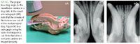
To capture the mandibular incisors and canines, place the patient in dorsal recumbency with the neck fully extended. Place the film as parallel to the plane of the mandible as possible, so that the film covers the entire intended area. Center the tube head on the patient's head, perpendicular to the film. Then rotate the tube head in the same vertical plane to an angle about 75 degrees to the film. This should be an accurate bisecting angle for the roots (Figures 6A-6C).


In large-breed dogs, the small size of the dental film may require the incisors to be exposed separately from the canines. In this case, the first view is taken with the front edge of the film sticking out just in front of the incisors. This film will image the incisors. To image the entire canine root, place the film so that the back edge is beyond the level of the second premolar. In larger breeds, this view does not typically image the coronal area of the incisors. Note that there may be a difference in exposure for these two views.
Maxillary incisors
The bisecting angle technique is used for imaging the maxillary incisors.7 In cats and most small-breed dogs, all six incisors can be exposed on one film. In large-breed dogs, left-and right-side views may need to be radiographed separately, especially if using digital sensors. In certain dogs (particularly dolichocephalic breeds), the lateral incisors may need to be imaged separately since they will be superimposed on the canines.9 In this case, move the tube head in the horizontal plane to properly image the lateral incisors.
As with the mandibular canines and incisors, the maxillary incisor roots curve backward to nearly a 45-degree angle in many cases.8,9 This means the roots have markedly different angles than do the crowns. Since the roots are typically the area of interest, remember to use the angle of the root and not the angle of the crown for your bisecting angle calculation.
To capture the maxillary incisors, place the patient in sternal recumbency with the neck extended and the head level with the table. Place the film in the mouth so that the upper canines are resting on it and a small amount of the film is in front of the incisors. Center the tube head directly in front of the patient's head, and angle it about 80 degrees to the film in the rostrocaudal plane, which is the approximate bisecting angle for the distally curved roots (Figures 7A & 7B).

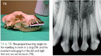
In some cases, the lateral incisor may be superimposed over the canine. Correct this overlap by keeping the tube head at the same angle in the rostrocaudal plane and rotating it about 30 degrees laterally in the horizontal plane.
Maxillary canines
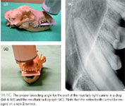
The technique for radiographing maxillary canines also uses the bisecting angle principle; remember to focus on the root rather than the tooth. Each maxillary canine must be imaged on a separate film8,9 because the root of the maxillary canine lies over the maxillary first and second premolars in dogs and over the maxillary second premolar in cats. If the canines are imaged by using one rostral view only, they will overlap with the premolars on the image.8,9 Furthermore, it is important to remember that the apex of the canine root is near the mesial root of the second premolar. So to image the entire root, the film needs to be placed distal to the second premolar.
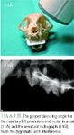
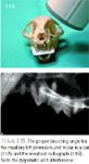
For these views, position the patient in sternal recumbency with the neck fully extended. Place the film in the mouth between the maxillary canines, with the front of the film behind the incisors but just in front of the canines. It is important to place the back edge of the film at least to the level of the second premolar. Start with the tube head centered straight on with the nose. In cats, the ideal angle for this radiograph is 80 degrees in the rostrocaudal plane and 20 degrees in the lateral plane (Figures 8A-8C).10 Likewise in dogs, 80 degrees in the rostrocaudal plane is the ideal angle.11 The lateral ideal is less clear-cut, but an angle between 20 and 30 degrees appears to give the best image (Figures 9A-9C).11 The 80-degree rostrocaudal angle compensates for the backward sweep of the canines, and the 20-degree lateral angle removes the premolar interference while minimizing distortion. (For a demonstration, see the video "Maxillary cuspid—dog" at www.vetmedpub.com/DentalXray3.)


Maxillary molars and premolars
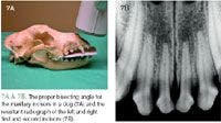
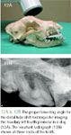
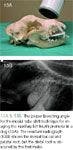
The techniques required to image maxillary molars and premolars are the most challenging of the veterinary dental radiographs. This is especially true of the maxillary fourth premolars. A precise bisecting angle technique7 is needed to achieve a high-quality radiograph of these teeth.

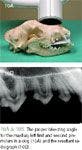
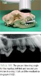
Position the patient in sternal recumbency with the neck extended. The cusp tips of the teeth to be imaged should be resting on the film, which is relatively flat against the palate. Center the tube head over the tooth to be imaged, and place it at about a 45-degree angle to the film. Proper technique will produce an excellent image of the premolars (Figures 10A & 10B) and an acceptable image of the molars, but this technique does cause superimposition of the mesial and palatal roots of the fourth premolar. In cats, this technique will give an excellent view of the second premolar and part of the third premolar, but the zygomatic arch interferes with the maxillary fourth premolar, third premolar, and first molar (Figures 11A & 11B).
CAPTURING HARD-TO-IMAGE TEETH
Certain teeth in dogs and cats are more difficult to image and require specialized imaging techniques.
Maxillary fourth premolar in dogs
To image the mesial roots of the maxillary fourth premolar separately, the tube head must be rotated around the dog's head in the horizontal plane. This is the most difficult technique in dogs because two precise angles are necessary to create an accurate image. Proper positioning will separate the mesial roots so they can be visualized independently.3,9
This technique uses the SLOB rule, which stands for same-lingual/opposite-buccal.5,6 The more buccal (or labial) object will move in the opposite direction as the tube shift, whereas the more lingual (or palatal) object will move in the same direction as the tube shift. This is also known as the tube shift technique.7 Two techniques can be used to create a good image.
The first option is the distal tube shift technique (Figures 12A & 12B). Rotate the tube head around the patient's cranium distally so it is pointing more toward the front of cranium at about a 30-degree angle. The resultant radiograph will reveal the mesial roots separately. In this case, the mesial-buccal root is imaged most mesial and the mesio-palatal root is imaged between the mesial-buccal and distal roots. This option is usually preferred because in most cases the entire tooth can be imaged on one film.


The second option is the mesial tube shift technique (Figures 13A & 13B). With this technique, the tube is shifted about 30 degrees mesially so that the tube head is pointed toward the back of the patient. The resultant view reveals the mesio-palatal root imaged mesial to the mesio-buccal root. The notable disadvantage with this technique is that the distal root is now superimposed over the first molar, so an additional exposure will be required to evaluate the distal root.


Maxillary fourth premolar in cats
In veterinary dental radiography, the most notable difference between dogs and cats is the technique required for imaging the maxillary cheek teeth.8 In dogs, high-quality radiographs of these teeth can be obtained with the standard bisecting angle technique. In cats, however, the zygomatic arch does not allow a clear view of the third and fourth premolars since the arch will be superimposed over these roots.3,8 Because of this limitation, two additional techniques are now being used to get a clear image of these tooth roots in cats—the extraoral technique and the acute angle technique.
Extraoral technique. The extraoral technique is difficult to master, but it allows the maxillary cheek teeth to be visualized without interference of the zygomatic arch or elongation of the roots (Figures 14A & 14B).12 Place the film on the table with the embossed dot facing up and the patient in lateral recumbency with the teeth to be imaged down on the film. Position the film so that the ventral aspect is just visible below the cusp tips of the teeth to be imaged. This positioning will ensure that most of the film is available to image the roots. Be sure that the film covers the entire arcade (second premolar to first molar) in the rostrocaudal direction. For this view, a size 4 film is helpful to reduce placement errors.
Next, place a radiolucent gag (e.g. a syringe) between ipsilateral canines to open the mouth relatively wide. Slightly rotate the patient's head so that the mandible is about 20 degrees above the maxilla. Then position the tube head so it points into the oral cavity, such that the cusp tips of the opposite arcade will be imaged about 3 mm below the root apices of the arcade to be imaged. The angle produced is about 25 degrees from perpendicular, which then creates the approximately 45-degree angle necessary to accurately depict the root length.12 Variation of the angle depends on the anatomy of the particular patient.
With the extraoral technique, the zygomatic arch is visualized apical to the tooth roots, giving a clear picture of the entire root system. Splitting the tooth roots (SLOB rule) is difficult to achieve in this view. In cases in which this is critical, use the acute angle technique instead.
An important point to remember when using the extraoral technique is that the film needs to be marked to distinguish right from left. This is because the embossed dot faces into the mouth, as opposed to out of the mouth as in the intraoral techniques. So when the films are viewed they will be interpreted as the contralateral arcade. In our practice, the embossed dots on dried films are filled in with a red permanent marker to denote that the extraoral technique was used. Other practices may mark an L or R on the film with a permanent marker or use small paper clip markers before exposure.
Acute angle technique. The acute angle technique is similar to the standard bisecting angle; however, the teeth are purposefully elongated to remove the zygomatic arch interference.3 This technique provides clearer splitting of the mesial roots of the upper fourth premolar than the extraoral technique does. Perform a standard bisecting angle technique with the beam angle at 30 degrees instead of 45 degrees.3 This technique removes the zygomatic arch interference but results in a slightly elongated image (Figures 15A & 15B). The mesial tube shift technique is preferred in cats because of the proximity of the third premolar mesially and the smaller first molar distally.

Mesial mandibular premolar teeth
As stated previously, most mandibular teeth can be imaged by using the parallel technique.7 But in some patients there is a problem with imaging the apices of the mesial premolars.3,8 Typically, this is the third premolar (especially the mesial root) in cats and the first and second premolars in dogs. The challenge with imaging these teeth is to avoid interference of the mandibular symphysis. A standard parallel view will not image these apices.
To image the entire arcade, it is often necessary to use the bisecting angle technique.7 This technique can be used to image the entire arcade or just the mesial premolars, with a second film using the standard parallel technique (which is more accurate) for the molars and distal premolars.
Position the film in the patient's mouth at about a 90-degree angle to the tooth roots so that the lingual edge of the film is touching the opposite mandible. Then place the beam perpendicular to the angle between the tooth roots and the film, which is about 45 degrees (Figures 16A-16C). Note that resultant image may suffer from slight elongation, which is considered a fair tradeoff for viewing the apices.
DEVELOPING DENTAL RADIOGRAPHS
Dental radiographs can be developed by using hand developing, automatic dental film processors, or standard radiograph processors. For instructions on automatic dental processing, refer to the operating manual for that piece of equipment. Using standard radiograph automatic processors for developing dental films is not recommended because of improper development and fixation as well as a chance of losing the film within the processor.
Regardless of the method chosen, the first step in developing dental radiographs is to remove the film from the packet. This must be done in a light-safe area to avoid exposing the film to light, which will destroy the image. To do this, carefully open the package by grasping the tag. There are three internal components: the film, a piece of black paper, and a lead sheet (Figure 17).6 The paper may either be in front of the film (toward the tube head) or wrapped around the film entirely. The lead sheet is behind the film. All three components feel different. Remove these contents and separate the film from the other pieces. Grasp the film only by the corner to avoid fingerprint artifacts.13 For hand development, place the film clip on the edge of the film before separation to avoid touching the film.
Hand development
Developing the film with chemicals manually, without the use of an automatic processor, is the least expensive and most common method of developing dental radiographs.5,6,14,15 This method is similar to the dip tank developing that was used historically for standard films.
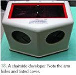
Hand developing can be performed in a darkroom by using household cups or bowls or in the operatory room with a chair-side developer. A chair-side developer unit has cups containing the chemicals for developing and fixing the film, which are visualized through a tinted filter (Figure 18). The advantages of chair-side developing include time efficiency and the allowance for continual patient monitoring by the technician during the development process.6,14,15


Hand developing methods use one of two different techniques to produce an image on the film. These methods are called time-temperature and sight developing.14 Both methods use a two-step rapid development solution.*** It is important to note that standard radiograph solutions are a poor substitute for dental film solutions since the time of development will be greatly increased and the quality of development and fixation will be inferior with standard solutions.14
Time-temperature development. With this method, continuously monitoring the temperature of the developing solution determines the required development time according to the manufacturer's recommendation.14 This method is the most scientifically correct but can be cumbersome.6
Sight development. This method is performed by dipping the film in the developer for a short time, removing it, and then critically examining it with the safe light or through the filter.6,14 This process is repeated until the first hint of an image appears, indicating the film is properly developed. Sight development has two distinct advantages over the time-temperature technique. First, continuous temperature monitoring is not necessary. However, the solution temperature rises during the day, especially if numerous films are being developed, which shortens development time. So unless frequent temperature readings are performed, this can result in overdeveloped films. Second and more important, the sight development method allows an experienced technician to adjust for minor technique errors by relatively overdeveloping or underdeveloping the film.14 This adjustment will not compensate for major errors but will avoid some retakes.
Submerge, rinse, and fix
With either hand-developing method, once the film is carefully removed from the packet, it is placed into the developer solution. For proper development, submerge the entire film for the allotted time, or until developed. After complete development, rinse the film by agitating it in distilled water for one minute, and then place it in the fixer. The film may be evaluated for a short period after complete submersion in the fixer for one minute. However, to archive the film for later viewing, it must be fixed for a minimum of 10 to 30 minutes depending on the condition of the fixer.5,14 The film can, however, stay in the fixer for a prolonged period without being adversely affected.
Rinse again and dry
It is necessary to thoroughly rinse the film after completing the fixation process. Proper rinsing requires the film to be placed in the water rinse for a minimum of 10 minutes. However, to achieve true archival quality, a 30-minute rinse is recommended.5,14 To avoid fixer solution dripping down from the clip and ruining the image, transfer the film to a clean clip and quickly rinse again before drying.14
Radiographs must be completely dried before storage or the films will stick together, resulting in film damage.5,14,15 Drying can be accomplished with a dental film dryer or a hair dryer. Alternatively, radiographs may be hung to air dry. However, if the air-drying method is used, allow a full 24 hours for complete drying. When drying multiple radiographs, it is beneficial to transfer them to a multifilm clip.
Monitor chemical quantities
Chemicals used in hand developing must be replaced frequently when using small cup quantities. Six ounces of developer will generally develop 10 to 15 size 4 films and even more of the smaller size 2 films before replenishment is necessary.5
Make copies
Regardless of appropriate development, fixing, and rinsing, some degradation of the film quality is expected over time. So I recommend taking high-quality digital photos of the radiographs and storing them in a computer folder that is routinely backed up. This will provide a permanent copy of the film and can also facilitate telemedicine with specialists or other veterinarians. Instructions on taking high-quality digital photos of dental films can be found on www.vetdentalrad.com by clicking on "How to Prepare Files" and then on "Digital Camera."
Exposure and development errors
Many potential opportunities for errors in dental radiography are directly related to developing or exposure. These errors result in either poor-quality or unreadable films. Common errors include underexposure or underdeveloping, overexposure or overdeveloping, underfixing, and underrinsing.5,6,14,15
Underexposure. Underexposed or underdeveloped radiographs appear washed out or light, which can result from insufficient exposure or developing time as well as exhausted developer. Correct the problem by increasing the development time or the exposure. If the problem persists, replace the developer and fixer solutions.
Overexposure. Overexposed or overdeveloped film results in a dark radiograph. Decreasing the exposure time usually solves the problem, but occasionally decreasing the development time may be preferred.
Underfixing. Extreme underfixing causes the film to blacken before viewing. Slight underfixing causes the radiograph to yellow over time. To avoid immediate film blackening, leave the film in the fixer for at least one minute before viewing. Long-term viewing ability (years) requires fixing the film for a total of 30 minutes.14
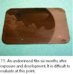
Underrinsing. Initially, a radiograph will not be adversely affected by insufficient rinsing. However, any fixer that remains on the film will cause it to brown over time, resulting in unreadable films (Figure 19). The problem with this error is that it is not discovered at the time of the procedure, so the films cannot be re-exposed. Avoid this problem by rinsing the film thoroughly. Current recommendations for proper rinsing include either 30 minutes in a rinse container or several minutes under running tap water.5,14


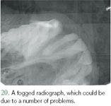
Other errors. Fogged or unclear radiographs (Figure 20) can occur secondary to a variety of problems that can be frustrating to identify and correct. The most common causes include old or exhausted solutions, old film, poor radiographic technique, light exposure, and improper light filter or developer type.14 In troubleshooting through this list, the cause will usually be elucidated. Light fogging (because of leakage) within a darkroom can be confirmed by placing a coin on an opened film for a few minutes and then developing the film. If an image of the coin is visible on the radiograph, there is a light leak.

CONCLUSION
Taking the time to properly position a patient, the film, and the beam head for dental radiographs is critical—the positioning and technique change greatly depending on the tooth. The development process is vital as well so that images come out clear and can be read for years to come. See the next article for advice on interpreting dental radiographs.
Author's Note: All photographs demonstrating positioning are shown with a standard dental film to optimize the visibility of tube head placement, film placement, and the correct angles between them. All radiographs except Figures 19 and 20 were obtained with a size 2 dental digital sensor to provide optimum print quality.
Editors' Note: Dr. Niemiec is a co-founder of the dental radiography consultation service VetDentalRad.com.
*For example, Gendex from Dentsply/Gendex Division.
**For example, Image-Vet 70 ACP from AFP Imaging, Corix Pro 70 from Dentalaire Products, and Provecta V from AllPro Imaging.
***For example, Insta-fix and Insta-neg from Microcopy.
Brook A. Niemiec, DVM, DAVDC, FAVD
Southern California Veterinary Dental Specialists
5610 Kearny Mesa Road, Suite B1
San Diego, CA 92111
REFERENCES
1. Holmstrom SE, Bellows J, Colmery B. AAHA Dental Care Guidelines for Dogs and Cats. J Am Anim Hosp Assoc 2005;41:277-283.
2. Niemiec BA, Gilbert T, Sabitino D. Equipment and basic geometry of dental radiography. J Vet Dent 2004;21:48-52.
3. Mulligan TW, Allen MS, Williams CA. Intraoral imaging techniques. In: Atlas of canine and feline dental radiology. Trenton, NJ: Veterinary Learning Systems, 1998;27-44.
4. Oakes A. Radiology techniques. In: Deforge DH, Colmery BH, eds. An atlas of veterinary dental radiology. Ames: Iowa State University Press, 2000;xxi-xxvi.
5. Holmstrom SE, Frost P, Eisner ER. Dental radiology. In: Veterinary dental techniques. 2nd ed. Philadelphia, Pa: WB Saunders Co, 1998;107-131.
6. Wiggs RB, Lobprise HB. Dental and oral radiology. Veterinary dentistry—principles and practice. Philadelphia, Pa: Lippincott-Raven, 1997;140-156.
7. Mulligan TW, Aller MS, Williams CA. Projection geometry. In: Atlas of canine and feline dental radiology. Trenton, NJ: Veterinary Learning Systems, 1998;15-22.
8. Niemiec BA, Furman R. Feline dental radiography. J Vet Dent 2004;21:252-257.
9. Niemiec BA, Furman R. Canine dental radiography. J Vet Dent 2004;21:186-190.
10. Gracis M. Radiographic study of the maxillary canine tooth in four mesaticephalic cats. J Vet Dent 1999;16:115-128.
11. Gracis M, Harvey CE. Radiographic study of the maxillary canine tooth in mesaticephalic dogs. J Vet Dent 1998;15:73-78.
12. Mulligan TW, Aller MS, Williams CA. Extraoral imaging techniques. In: Atlas of canine and feline dental radiology. Trenton, NJ: Veterinary Learning Systems, 1998;23-26.
13. Mulligan TW, Aller MS, Williams CA. Technical errors and troubleshooting. In: Atlas of canine and feline dental radiology. Trenton, NJ: Veterinary Learning Systems, 1998;45-64.
14. Niemiec BA, Sabitino D, Gilbert T. Developing dental radiographs. J Vet Dent 2004;21:116-121.
15. Mulligan TW, Aller MS, Williams CA. Basic equipment needs. In: Atlas of canine and feline dental radiology. Trenton, NJ: Veterinary Learning Systems, 1998;7-14.